How to install your system🔗
Topside🔗
The topside should be placed outdoors with an open view to the sky, to easily achieve GPS lock. The forward direction of the topside box should be in the direction you define as forward. If you are using an antenna, make sure the forward direction of the antenna aligns with the forward direction of the topside. If on a boat, typically forward aligns with the boats heading.
Antenna🔗
The antenna can be placed anywhere up to 10m from the topside housing (limited by cable length). Make sure its forward direction aligns with the forward direction of the topside box. If this is not possible, make sure you enter the deviation in the Baseline settings in the GUI. See System Configuration
Tip
By the antenna base is meant the joining point of the three prongs with the receivers at their ends.
| Alignment | Ensure that the 'Forward' direction of the antenna as defined by a label on one of its prongs (see also the figure below) is aligned with the 'Forward' direction of the topside housing (indicated by a label on the lid). If it is not possible to physically align them, in Baseline -> Antenna configuration -> Advanced settings, specify the clockwise angle in degrees from the forward axis of the topside to the forward axis of the antenna. If this alignment is not carried out, the global position outputted by UGPS G2 will be incorrect. |
| Line-of-sight | Ensure that there will be line-of-sight between the antenna and locator. |
| Antenna depth | Ensure that the base of the antenna is at a depth of at least one metre (as indicated by a label upon the top folding joint of the pole of the antenna), to avoid acoustic disturbance. The depth of the antenna base (relative to the sea surface) must be specified in Baseline -> Antenna configuration -> Advanced settings -> Antenna depth. If it is not, both the acoustic and global positions may be incorrect. |
| Antenna stability | Secure the antenna tightly to the vessel using the provided Ram Mount. |

Note
Directivity : the antenna and locators are omnidirectional, that is, signal strength should be good in all directions
Receivers🔗
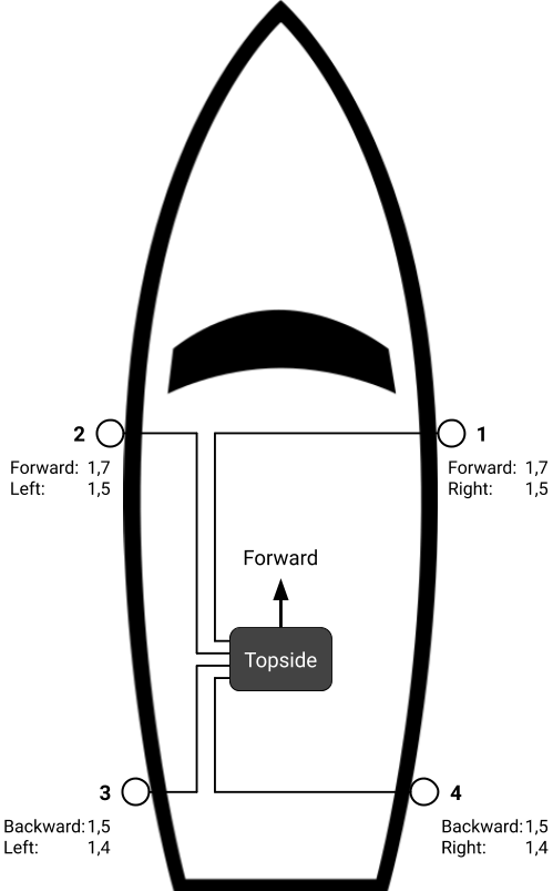
Loose receivers can be placed anywhere up to 100m from the topside housing. Go through the following, and configure the placement of the receivers in the graphical pane at Baseline -> Receiver and range configuration so that their positions relative to the origin and their depths are correct. See System Configuration
| Line-of-sight | Ensure that all the receivers will have line-of-sight to the locator. |
| Separation | Ensure that the receivers are not too close, and are not all in a line. A grid of 2x2 metres should typically be sufficient for good performance, but experiment with different configurations if you experience sub-optimal performance. |
| Depth | Place the receivers at a depth of at least a metre, to avoid acoustic disturbance. |
| Stability | Consider adding some weight to the receiver cables just above the receivers. |
Note
Directivity : The receivers and locators are omnidirectional, that is, signal strength should be good in all directions
The figure below indicates a typical loose receiver configuration when the topside unit is upon a boat. The receivers hang from the side of the boat. The origin of the the acoustic frame is in this case a point on the topside unit.

Locator setup🔗
Select the type of locator (U1, A1, or D1) which you are using, and which channel you wish to use.
No matter what locator that is in use, it always need to be placed within line of sight from the receivers. This will in most cases be somewere on top of the unit that is to be tracked.
Locator U1🔗
As the U1 is a wireless locator it can easily be mounted on your vehicle with the included bracket.
- Remember to charge the locator for at least 7 hours before use with a 5V/2A charger.
- Use the rotary switch at the back of the U1 (screw the lid completely off to access the switch) to adjust which channel you will be using. Channel 3 is a good option. Remember to adjust the channel in the GUI's Settings
Locator A1🔗
The A1 needs to be physically connected to the G2 Topside, either directly or through a full system integration. For wiring details of the A1, se [locator-A1]A1.
If you are using the A1 on a Bluerov, see Bluerov integration
Locator D1🔗
The D1 comes with 50m integrated cable that is coupled directly into the topside box.
For more information on the D1, go to Locator D1