PD formats🔗
The DVL can output PD-compatible formats for integration with systems that already support these formats.
PD formats are data formats. They can be available over different transports depending on model, software version, and configuration.
For new integrations, the TCP JSON API is usually the easiest starting point:
Supported formats🔗
| Format | Status | Notes |
|---|---|---|
| PD4 | Supported | Supported over TCP and serial for DVL A50, DVL A125, DVL A100, and DVL A250. |
| PD6 | Supported | Supported over TCP and serial for DVL A50, DVL A125, DVL A100, and DVL A250. |
| PD0 | Planned for DVL A100/A250 | Not available yet. Planned over TCP and serial when ready. |
Transport support🔗
| Format | TCP | Serial | Models |
|---|---|---|---|
| PD4 | Yes | Yes | DVL A50, DVL A125, DVL A100, DVL A250 |
| PD6 | Yes | Yes | DVL A50, DVL A125, DVL A100, DVL A250 |
| PD0 | Planned | Planned | DVL A100, DVL A250 |
PD4 and PD6 over TCP are always enabled. The TCP port is configurable in the web GUI.
Serial PD output is configured through the serial output protocol setting:
When to use PD formats🔗
Use PD formats when integrating with software or systems that already expect PD0, PD4, or PD6 output.
For custom software integrations, use the TCP JSON API unless the receiving system specifically requires a PD format:
PD6🔗
PD6 support allows integration with equipment that already has a PD6-compatible interface, reducing the need to create a driver based on the Water Linked serial protocol.
PD6 is supported for output over serial and Ethernet. PD6 over TCP is always enabled. The port in use is configurable in the web GUI. The default port is TCP 1037.
The serial output can be configured to output PD6 using the serial output protocol setting.
Command overview🔗
Sentences TS, BI, and BD are filled with relevant numbers. All other sentences are set to zero values.
Timing and scaling data (TS)🔗
:TS,YYMMDDHHmmsshh,SS.S,+TT.T,DDDD.D,CCCC.C,BBB <CR><LF>
| Field | Explanation | Value |
|---|---|---|
| YYMMDDHHmmsshh | Year, month, day, hour, minute, second, hundredths of seconds | Report timestamp |
| SS.S | Salinity in parts per thousand (ppt). | Always 0 |
| DDDD.D | Depth of transducer face in meters. | Always 0 |
| CCCC.C | Speed of sound in meters per second. | Configured speed of sound |
| BBB | Built-in Test (BIT) result code. | Always 0 |
Bottom track, instrument referenced velocity data (BI)🔗
:BI,±XXXXX,±YYYYY,±ZZZZZ,±EEEEE,S <CR><LF>
| Field | Explanation | Value |
|---|---|---|
| ±XXXXX | X-axis velocity data in mm/s | Current speed |
| ±YYYYY | Y-axis velocity data in mm/s | Current speed |
| ±ZZZZZ | Z-axis velocity data in mm/s | Current speed |
| ±EEEEE | Error in velocity data in mm/s | Current error |
| S | Status of velocity | A = good. V = bad |
Note
Axis used in the BI sentence is the vehicle frame.
Bottom track, earth referenced distance data (BD)🔗
:BD,±EEEEEEEE.EE,±NNNNNNNN.NN,±UUUUUUUU.UU,DDDD.DD,TTT.TT <CR><LF>
| Field | Explanation | Value |
|---|---|---|
| ±EEEEEEEE.EE | East distance in meters. | Always 0 |
| ±NNNNNNNN.NN | North distance in meters. | Always 0 |
| ±UUUUUUUU.UU | Upward distance in meters. | Always 0 |
| DDDD.DD | Range to bottom in meters | Current altitude |
| TTT.TT | Time since last good velocity estimate in seconds. | Always 0 |
Bottom track, ship referenced distance data (BS)🔗
- In the 2.4.0 software release, the BS values are always zero.
- As of the 2.4.4 software release, the BS values are given by the actual velocity.
:BS,±TTTTTTTT.TT,±LLLLLLLL.LL,±NNNNNNN.NN,S <CR><LF>
| Field | Explanation | Value |
|---|---|---|
| ±TTTTTTTT.TT | Transverse movement, (+ = Port to Starboard velocity relative to bottom) in mm/s | Y axis velocity |
| ±LLLLLLLL.LL | Longitudinal movement, (+ = Aft to Forward velocity relative to bottom) in mm/s | X axis velocity |
| ±NNNNNNN.NN | Ship velocity away from bottom in mm/s | Z axis velocity |
| S | Status of velocity | A = good. V = bad |
Example output🔗
:SA, +0.00, +0.00,  0.00
:TS,22020812061800, 0.0, +0.0,   0.0,1475.0,  0
:WI,    +0,    +0,    +0,    +0,V
:WS,    +0,    +0,    +0,V
:WE,    +0,    +0,    +0,V
:WD,       +0.00,       +0.00,       +0.00,   0.00,  0.00
:BI,  +123,  -420, +2000,    +0,A
:BS,  -420,  +123, +2000,A
:BE,    +0,    +0,    +0,V
:BD,       +0.00,       +0.00,       +0.00,   5.32,  0.00
PD4🔗
The PD4 string is intended for use with equipment that already has a PD4-compatible interface, reducing the need to create a driver based on the Water Linked serial protocol.
PD4 is supported for output over serial and Ethernet. PD4 over TCP is always enabled. The port in use is configurable in the web GUI. The default port is TCP 1038.
Note
PD4 format support was added in software release 2.5.2 and is experimental. Please give feedback on this feature.
Data format🔗
PD4 is a binary format where fields are defined by their position in one message. Data fields which use more than one byte are LittleEndian encoded.
| Byte(s) | Data type | Used | Unit |
|---|---|---|---|
| 0 | DVL Data ID 7Dh | y | |
| 1 | Data structure (always equal to 0) | y | |
| 2,3 | Number of bytes | y | |
| 4 | System Config (0x101000111) | y | |
| 5,6 | X velocity bottom | y | mm/s |
| 7,8 | Y velocity bottom | y | mm/s |
| 9,10 | Z velocity bottom | y | mm/s |
| 11,12 | E velocity bottom | y | mm/s |
| 13,14 | BM1 range to bottom | y | cm |
| 15,16 | BM2 range to bottom | y | cm |
| 17,18 | BM3 range to bottom | y | cm |
| 19,20 | BM4 range to bottom | y | cm |
| 21 | Bottom status | y | bool |
| 22,23 | X-Velocity reference layer | n | |
| 24,25 | Y-Velocity reference layer | n | |
| 26,27 | Z-Velocity reference layer | n | |
| 28,29 | E-Velocity reference layer | n | |
| 30,31 | Reference layer start | n | |
| 32,33 | Reference layer end | n | |
| 34 | Reference layer status | n | |
| 35 | Time of first ping - hour | y | hours |
| 36 | Time of first ping - minute | y | minutes |
| 37 | Time of first ping - second | y | seconds |
| 38 | Time of first ping - hundredths | y | centi-seconds |
| 39,40 | Bit result | n | |
| 41,42 | Speed of Sound | y | m/s |
| 43,44 | Temperature | n | |
| 45,46 | Checksum | y | N/A |
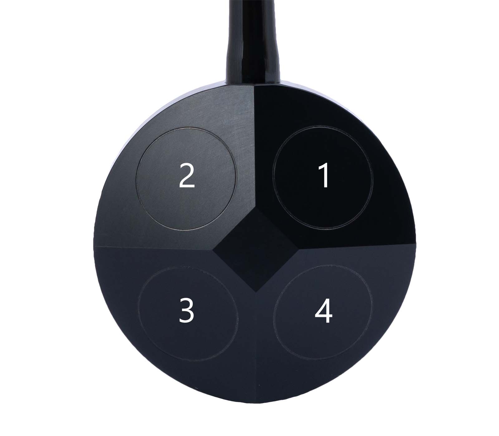
BM1-BM4 mapping🔗
To use BM1-BM4 correctly, use this translation. The numbering comes from the transducer numbering shown in the image below.
- BM1 is transducer 3.
- BM2 is transducer 1.
- BM3 is transducer 4.
- BM4 is transducer 2.
Transducer numbering and protocol IDs
Mechanical/transducer diagrams number the transducers from 1 to 4. In protocol messages and diagnostic logs, the transducer id uses zero-based numbering from 0 to 3. The id is therefore the transducer number minus 1.
PD0🔗
PD0 is planned for DVL A100 and DVL A250. It is not available yet.
When ready, PD0 is planned for both TCP and serial output.
-
Indicates that the velocities are in ship coordinates, tilt is used, three-beam is not computed, and the frequency is 600 kHz. ↩